
About a year after I got my 3D printer, I came across the Mostly Printed CNC on thingiverse, and immediately followed up on Ryan Zellars’ site. I was instantly into the idea of building one for myself.
I started printing the plastic parts, collecting the bits and bobs needed, ordering stepper motors, a suitable spindle motor, and looking for appropriate steel tubes. A complete BOM, sources, and costs will follow. I had already printed the plastic parts of the machine to fit for 25 mm steel tubes, but the ones I could eventually find locally were 26 mm. This came down to a lot of filing. The steel tubes were sold in 6 m lengths, so using the online calculator on Ryan’s site, I calculated the dimensions of the parts to come to the sum of 6 m. That resulted in a machine with 80 cm sides and slightly less than 50 cm height, which gives me a decent working area of roughly 54 times 54 cm, and 13 cm z-depth.
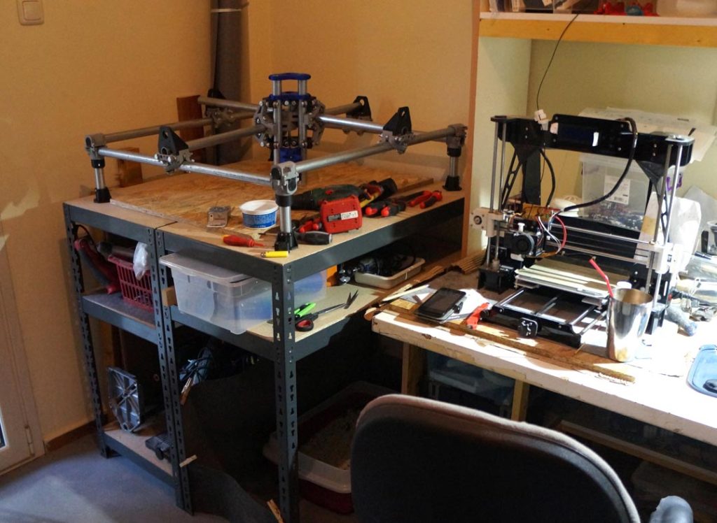
Assembling the machine is pretty well documented on Ryan’s site. Before tightening the assembly, I had to make a rigid base to mount the machine on. This base also serves for fixing work-pieces on, so I opted for a stack of two melamine boards of 16 mm thickness, each 80 times 80 cm wide.
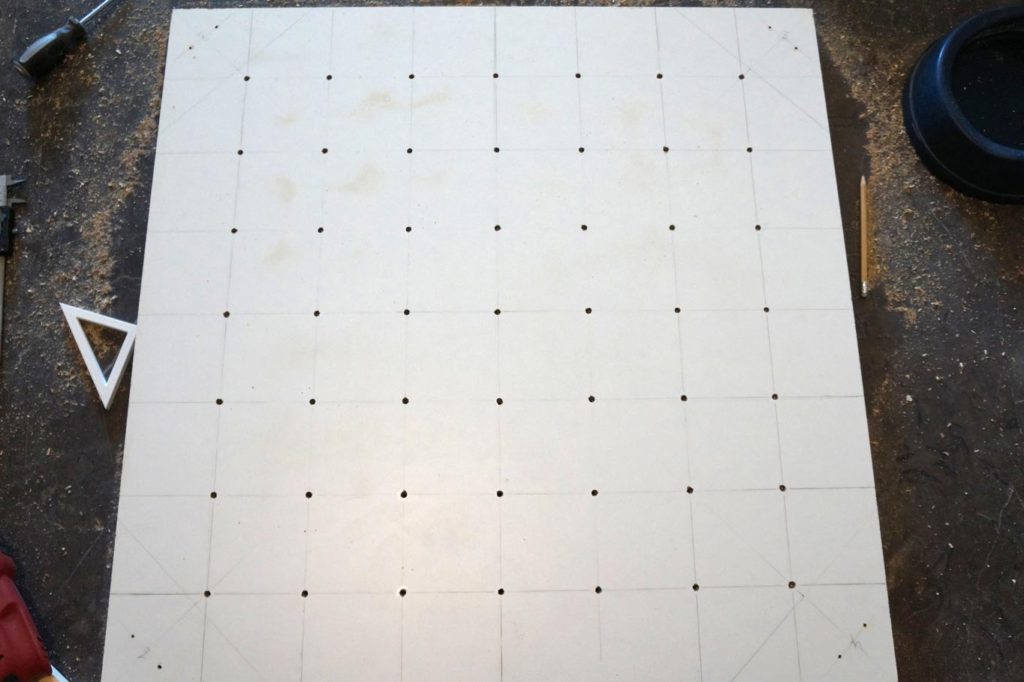
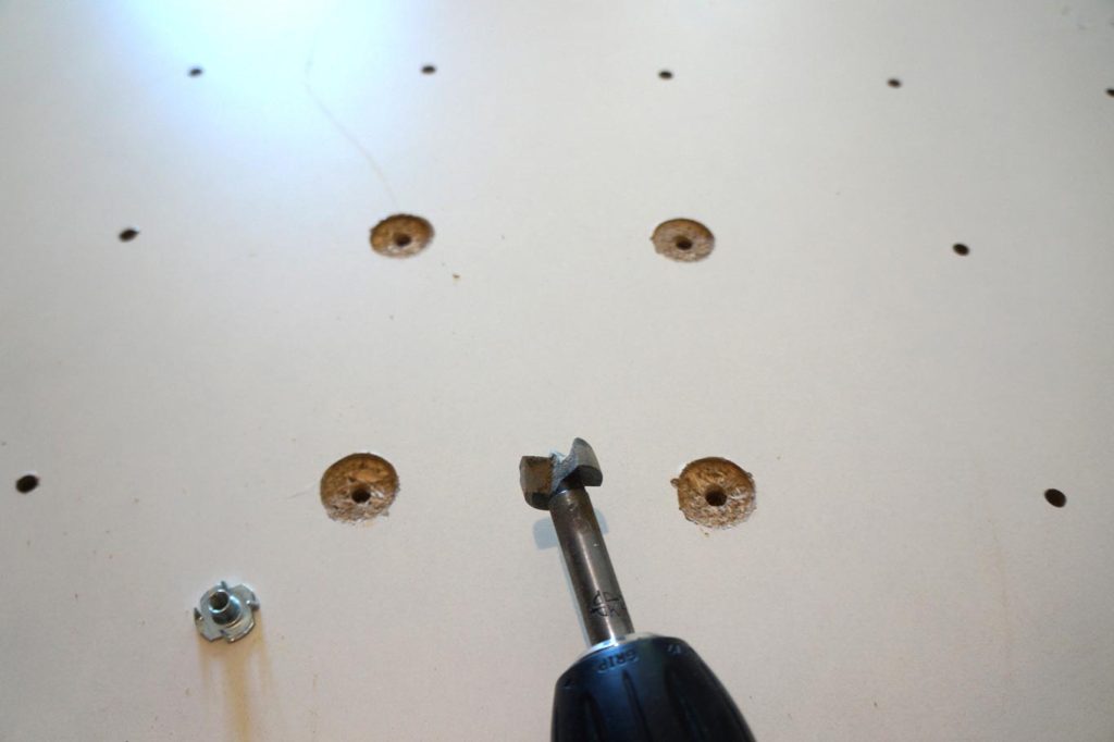
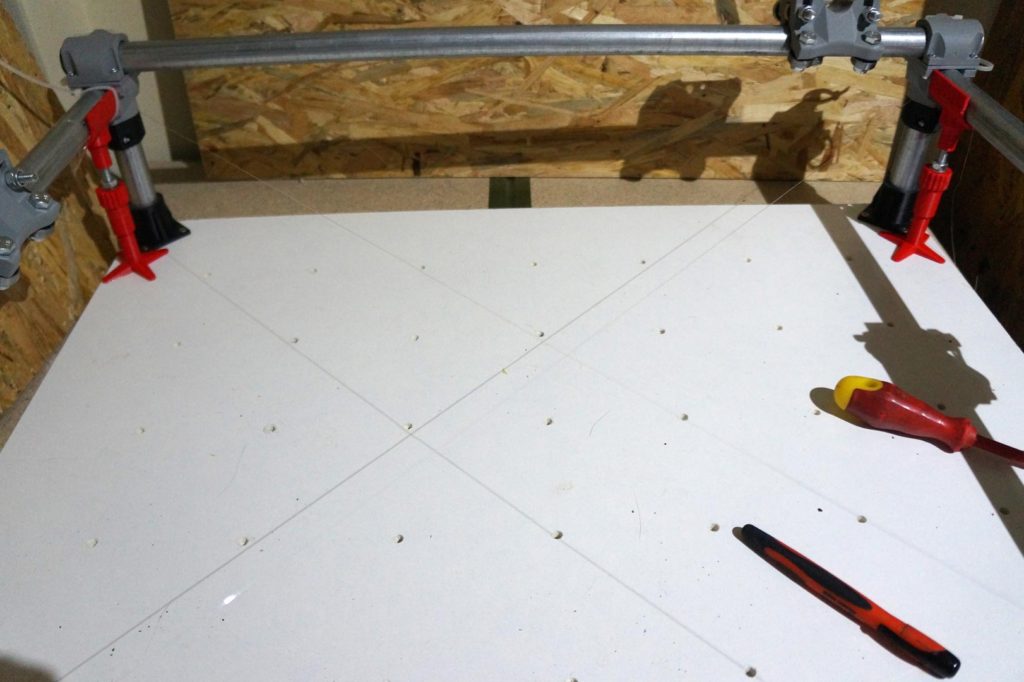
Holes were drilled in both boards at 10 cm spacing, and the underside of the top board was routed to receive M5 screw inserts at the positions of the holes, as shown in the picture below. The two boards were glued and screwed together, burying the screw inserts in between. This way, M5 screws can be inserted from the top board and screwed tightly in place into the inserts. These screws then hold fixtures which hold the work-pieces. More on that in some future post.
When it comes to attaching and fixing the assembly of the machine to the base, there are some things to consider. Firstly, all the rails have to be parallel to the base, and at the same height, so that the middle assembly moves the tool at the same height over the entire work surface, and secondly, adjacent rails have to be at a right angle to each other, otherwise the geometry of the work produced will not match the design.
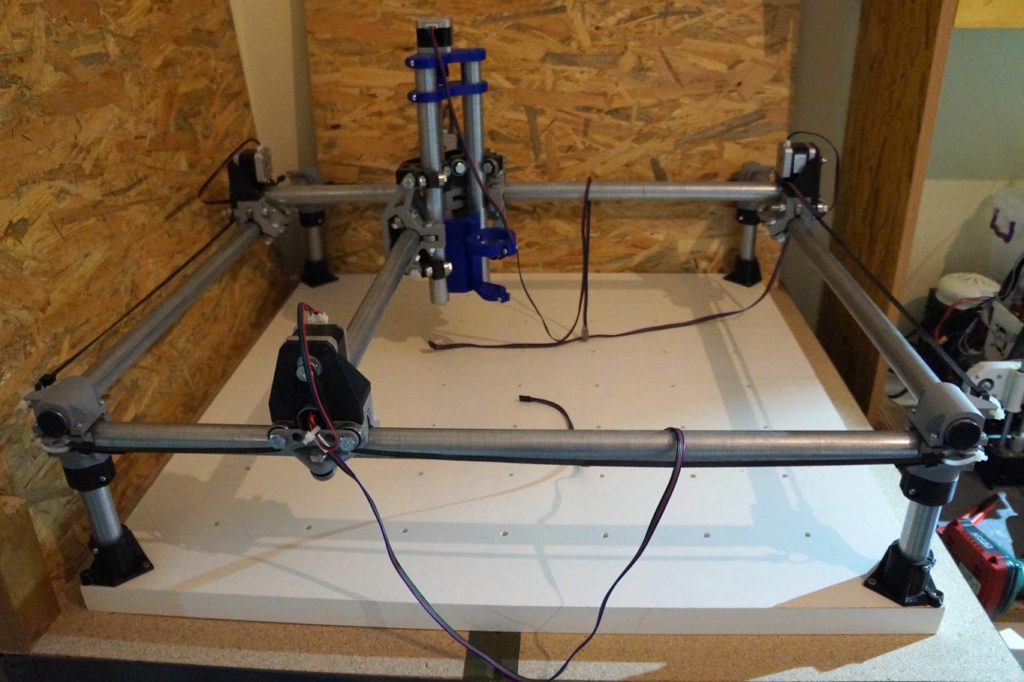
To make this task easier, and to be as accurate as possible, I designed some alignment tools to adjust the height and positions of the corners. They are designed in OpenSCAD to be customisable to your needs, and the way they are used is described on the design’s page. When heights and squareness are properly aligned, the corners are screwed into the base, the screws of the loose assembly are tightened, and the stepper motors, pulleys, belts and wiring are added. {pfew!}
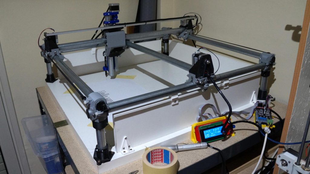
The MPCNC is driven by an Arduino Mega with RAMPS board and suitable stepper motor drivers, such as the DRV8225 boards. This setup is inexpensive and common in homemade 3D printers. The machine is controlled through the Marlin firmware, also widely used in homemade 3D printers, slightly adapted and provided for download on Ryan’s site. The Arduino Mega can be plugged over USB to a PC, and Repetier-Host or similar software, can be used to control it through g-code commands. Alternatively, a g-code file can be written to SD card and transfered to the Arduino Mega for execution.
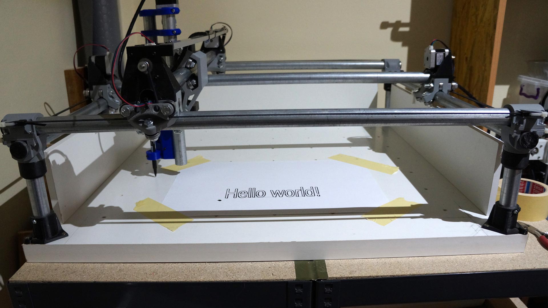
In the first test-runs of the machine I’ll be using a pen and not a spindle as the tool head, until I’m sure I know what I’m doing. I started off by making a 2D design in inkscape, turning that into paths in Estlcam, writing the produced g-code onto the SD card, and printing it on the MPCNC. Simple, isn’t it?
So, some hundred working hours later and I’ve got myself my first homemade robotic thingy, moving pretty precisely to some pre-programmed digital design. Ever felt like the possibilities are endless?

Now, imagine having a spindle on there, carving through wood or aluminum. That’s going to be a lot of dust and a lot of noise. So, until I build myself a good enclosure and dust extraction, I’ll have to make do with a pen.